SkyRelay Conduit
User Manual
Contents
1. Overview
Conduit is firmware that connects your drone’s flight controller (FC) to SkyRelay and your ground control station (GCS) over a cellular network. It runs on hardware installed on the drone, including LilyGo boards and Raspberry Pi.
LilyGo boards, etc.
QGroundControl
Telemetry travels to users; commands follow the same path back to the drone.
Compatible flight controllers include ArduPilot (Copter, Plane, Rover) and PX4 with a MAVLink telemetry port. Feature coverage varies by autopilot, software version, and vehicle type. Keep the flight controller at its default system ID of 1 (SYSID_THISMAV on ArduPilot, MAV_SYS_ID on PX4); commands sent from your SkyRelay account are addressed to system 1.
2. Hardware Setup
K01 kits arrive assembled. Continue with Installation. For a self-assembled device, follow the instructions for your board below.
LilyGo T-SIM7600NA
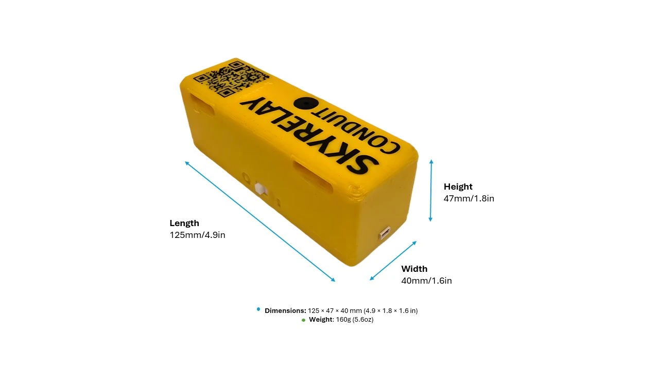
K01 — Assembled Kit
| Item | Qty | Description |
|---|---|---|
| SkyRelay Conduit | 1 | Fully assembled unit — SIM, battery, buzzer, UART board, antennas, case, and firmware installed |
| UART-to-FC Cable | 1 | 4-pin SH1.0, connects Conduit to the flight controller telemetry port |
| Mounting Kit | 1 | Non-slip battery straps |
| Activation Card | 1 | QR code for device registration and dashboard access |
K02 — Assembly Kit
You need a LilyGo T-SIM7600NA board, an 18650 battery, a case, and the following kit components:
| Item | Qty | Description |
|---|---|---|
| Hologram SIM | 1 | Pre-provisioned nano-SIM |
| Buzzer + Harness | 1 | Active piezo buzzer, 3-pin Dupont connector with cables |
| UART Pan Board + Harness | 1 | 4-pin UART breakout for the flight controller connection, 2-pin Dupont connected with cables |
| UART-to-FC Cable | 1 | 4-pin SH1.0, connects Conduit to the flight controller telemetry port |
- Attach the LTE and GPS antennas.
- Insert the Hologram SIM in the nano-SIM slot on the underside of the board.
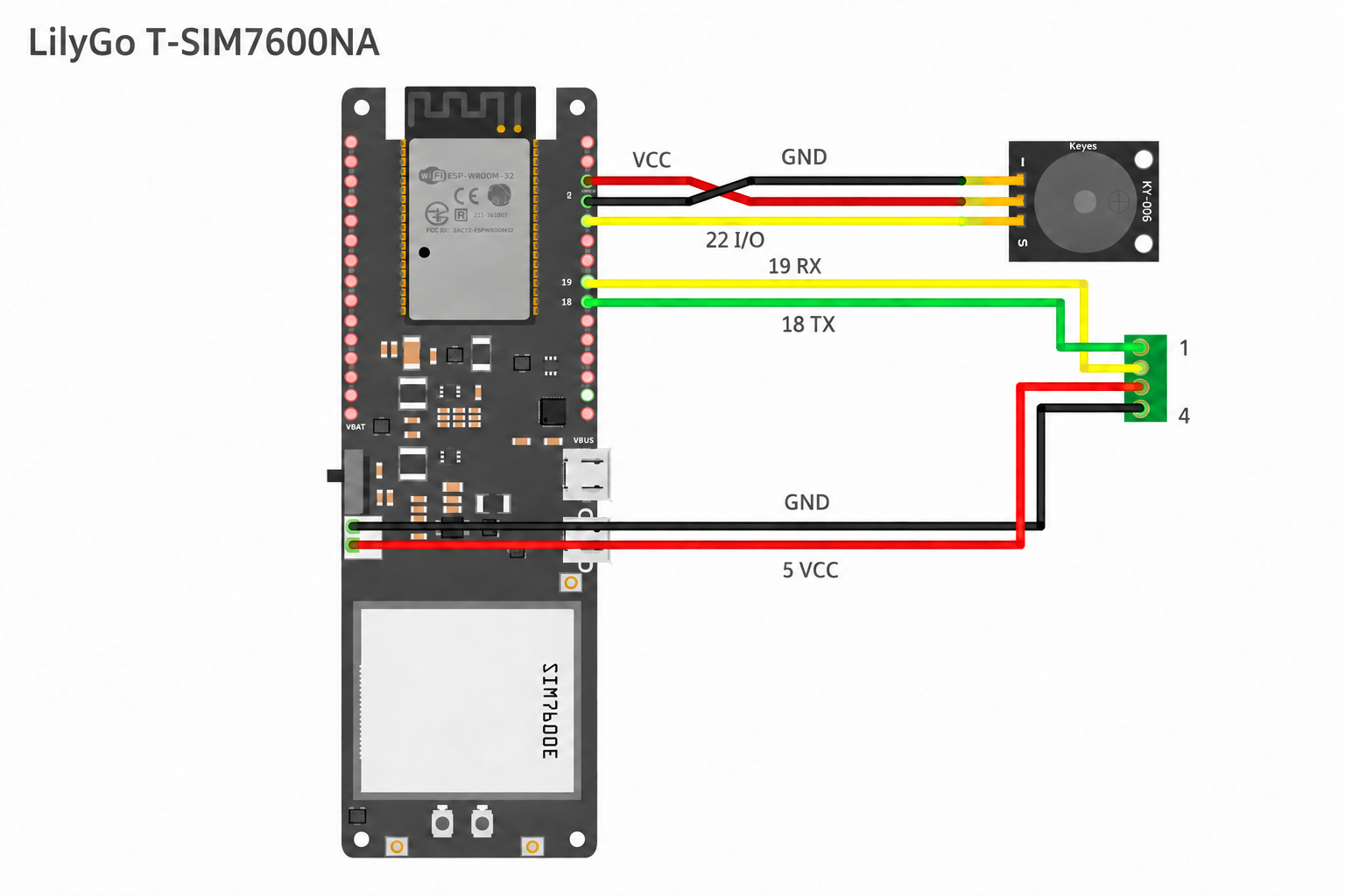
- Solder the buzzer harness and UART breakout board connections shown in Figure 3 and the table below.
- Fit the 18650 battery and case.
- Install Conduit over USB, selecting T-SIM7600NA.
Flight Controller and Buzzer Wiring
| Signal | Connection |
|---|---|
| FC UART TX/RX | GPIO 18 (Conduit TX), GPIO 19 (Conduit RX) via the UART breakout board |
| Ground | GND via the UART breakout board |
| FC 5V | Through the UART breakout board to the battery input — charges the 18650 in flight |
| Buzzer | I/O → GPIO 22, V → 3.3V, G → GND |
Power
USB-C or the FC cable’s 5V supply powers the board and charges the 18650 battery. The battery supplies backup power when external power is lost.
Conduit reports battery voltage, estimated charge level, and external power status.
LilyGo T-PCIE 16M
You need a T-PCIE 16M board (revision V1.2 or later — V1.1 boards use a different power chip and are not supported), a SIM7600NA modem card, LTE and GPS antennas, a Hologram nano-SIM, an 18650 battery, a buzzer with harness, an FC cable, and a case.
- Install the modem card in the mini-PCIe socket. Connect the LTE antenna to MAIN and the GPS antenna to GPS/GNSS.
- Set DIP switches 1 and 2 ON and 4 OFF.
- Insert the SIM.
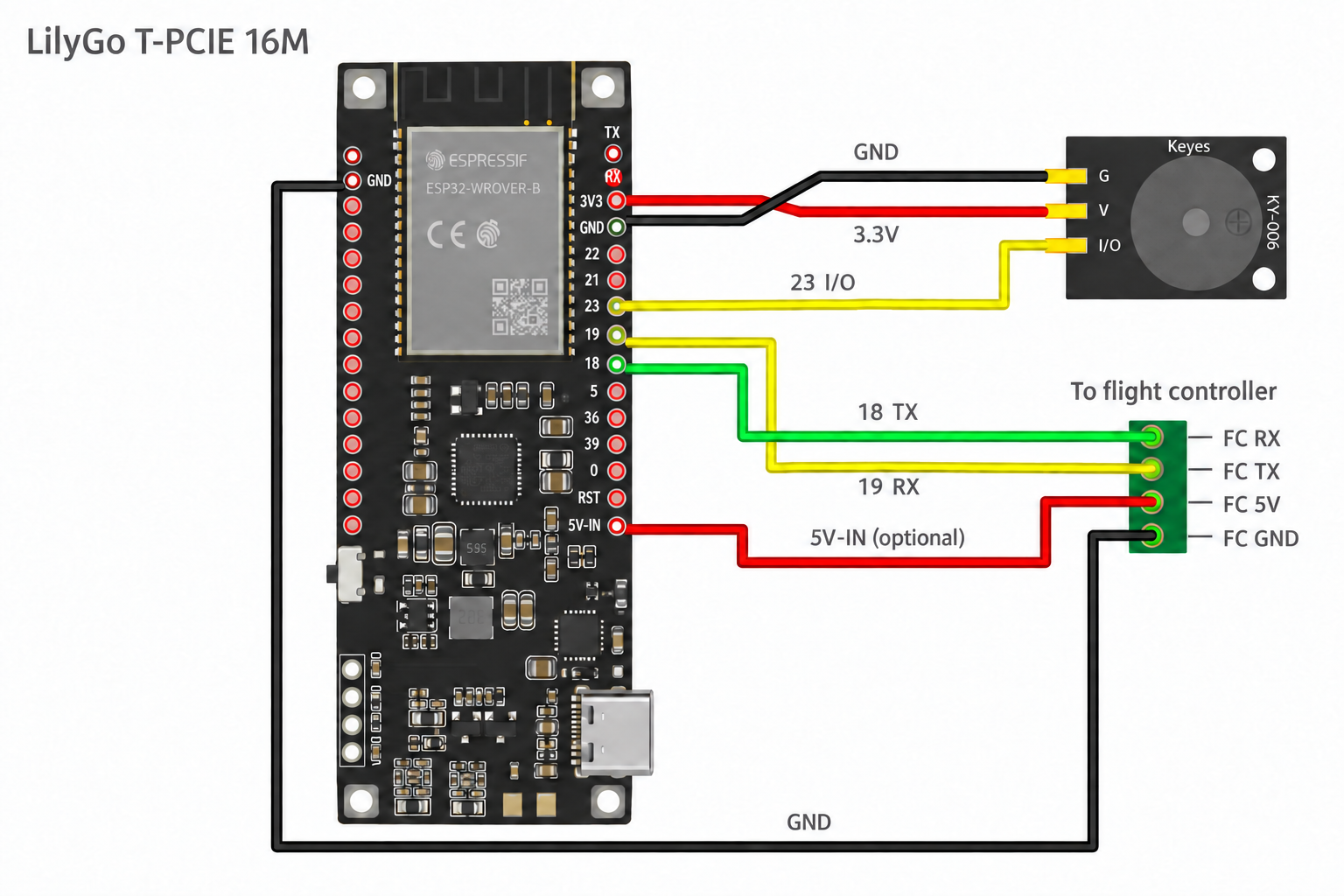
- Solder the FC cable to the header pins using Figure 4 and the table below.
- Connect the buzzer: I/O → GPIO 23 (right header, 7th from top), V → 3.3V, G → GND.
- Fit the 18650 battery and case.
- Install Conduit over USB, selecting T-PCIE 16M.
Flight Controller Wiring
Header positions are counted from the top with the USB-C port at the bottom.
| Cable Signal | T-PCIE Pin | Header Location | FC Side |
|---|---|---|---|
| TX (Conduit transmit) | GPIO 18 | Right header, 9th from top | FC RX |
| RX (Conduit receive) | GPIO 19 | Right header, 8th from top | FC TX |
| GND | GND | Left header, 2nd from top | FC GND |
| 5V (optional — powers the board and charges the battery from the FC) | 5V-IN | Right header, bottom pin (below RST) | FC 5V |
Power and Buttons
External power runs the board and, when the supply can spare the current, charges the 18650 battery. The battery supplies backup power when external power is lost. If the FC’s 5V supply is limited, the battery may help carry the board during heavy cellular activity instead of charging.
Conduit reports battery voltage, estimated charge level, and external power status.
Auto power-off. If the flight controller has been connected and then stops sending data for 5 minutes, the T-PCIE turns itself off completely to save the battery. Reconnecting the flight controller within that time cancels it. Hold PWR for 1 second to turn the board back on.
- PWR — hold for 1 second to power on.
- EN — press to reset.
3. Installation
1. Activate the Device
Activate your device through your SkyRelay account. K01 kits include a QR code on the case and activation card.
2. Connect the Flight Controller
Use the wiring table for your board: T-SIM7600NA or T-PCIE 16M.
FC Cable Connector
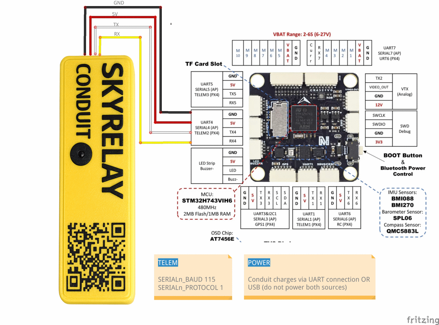
The 4-pin UART-to-FC cable must match your FC's telemetry port pinout. Order the pins in the connector as shown in Figure 5:
- Power and ground go to their counterparts
- Conduit RX → FC RX, Conduit TX → FC TX (the cables are reversed inside the case)
3. Configure the Telemetry Port
The Conduit communicates with the flight controller over MAVLink serial at 115200 baud. Set the parameters as follows, where n represents the serial port on your flight controller:
- ArduPilot (e.g., SERIAL2):
SERIALn_PROTOCOL = 2,SERIALn_BAUD = 115 - PX4 (e.g., TELEM2):
MAV_1_CONFIG = TELEM 2,SER_TELn_BAUD = 115200
4. Mount the Device
Secure the device to the airframe with foam padding and straps. Keep it clear of the aircraft’s GPS receiver and antennas.
5. Power On
Turn on the device. The buzzer plays HI at startup and K when connected to the cloud. See Buzzer Codes for the tone patterns.
6. Check the Connection
Open your SkyRelay account and confirm that the device is online and receiving flight-controller data. Check the reported position and battery level before use.
4. Connect Your GCS
Cellular (LTE)
Your GCS reaches Conduit through the SkyRelay private network, not the open internet. Enroll each computer, phone, or tablet that runs your GCS once (see Enroll Your Device), then:
- Make sure the device is connected to the private network (the Tailscale app shows Connected).
- In your GCS, add a UDP connection using the host and port shown for your Conduit in your SkyRelay account.
Enroll Your Device
Each device that runs your GCS needs its own enrollment — signing in to SkyRelay is not enough. You also need access to the Conduit: owners have it; other people must be approved on the Private Network page.
- Install the Tailscale app on the device from tailscale.com/download.
- In your SkyRelay account, open Private Network and click Enroll GCS.
- Enter a name for the device (for example, “Flight laptop”) and choose its type.
- Choose an enrollment path:
- Desktop command (Windows, Mac, Linux) — click Create enrollment. SkyRelay shows a single-use command. Copy it and run it on that device in a terminal (Command Prompt or PowerShell on Windows; the Mac and Linux command starts with
sudo). Then click Check connection on the device’s card. - Tailscale app / Auth ID (iPhone, iPad, Android, or any desktop) — in the Tailscale app, choose an alternate (custom) coordination server and enter the SkyRelay server address shown in the dialog. Begin signing in, copy the Auth ID that Tailscale shows, paste it into SkyRelay, and click Confirm and enroll.
- Desktop command (Windows, Mac, Linux) — click Create enrollment. SkyRelay shows a single-use command. Copy it and run it on that device in a terminal (Command Prompt or PowerShell on Windows; the Mac and Linux command starts with
- The device appears under Enrolled GCS clients.
Check that your device is connected
- On the Private Network page, the device shows Online.
- On the device, the Tailscale app shows Connected, or run
tailscale statusin a terminal. - To check the private-network tunnel, run
tailscale ping <host>with the host shown for your Conduit. Apongreply means the tunnel to SkyRelay works. It does not confirm that your Conduit is online or that you have access to it — telemetry arriving in your GCS is the final check.
Bluetooth Maintenance
Use a local Bluetooth Classic (SPP) connection for maintenance with QGroundControl or Mission Planner. Conduit does not appear in BLE scanner apps.
Bluetooth is for maintenance on the ground only. Conduit disconnects the Bluetooth link when the aircraft arms and refuses new connections until it is disarmed. Bluetooth GCS access can be turned off in Settings → GCS Relay.
- After powering on, wait up to 30 seconds (longer if there is no cellular signal) for Conduit to appear as
conduit-NNNN, where NNNN is the device ID. - In your phone or laptop’s Bluetooth settings, pair with
conduit-NNNN. - Select the Bluetooth Classic connection or Bluetooth serial port in your GCS.
Reduce Cellular Data Usage
- GCS Relay — turn off cellular MAVLink forwarding when unused; cloud telemetry continues.
- Data Saver — enable packet batching to reduce cellular data usage.
Network RTK
With Network RTK configured in your SkyRelay account, Conduit sends positioning corrections to the flight controller over MAVLink. An RTK-capable GPS receiver is required.
5. Buzzer and Recovery
Signal-loss Alert
Enable Alert on Signal Loss in Settings to sound SOS when the cloud connection is lost. The setting is saved across restarts. The alert stops when the connection returns.
Locate a Lost Drone
Activate the lost-drone buzzer from your SkyRelay account to help locate the aircraft by sound. A cellular connection is required to activate it.
FC/ESC Buzzer
During SOS, and when you press TEST BUZZER, Conduit also sends a locator tone to a connected flight controller while the aircraft is disarmed. This follows the same Buzzer setting and works even with no buzzer fitted to the Conduit. For ArduPilot with DShot ESCs, include DShot in NTF_BUZZ_TYPES to sound the tone through the motors.
QR Recovery — K01 Kit
A finder can scan the QR code on the K01 case to initiate contact with the operator.
Buzzer Codes
| Event | Pattern | Trigger |
|---|---|---|
| Power on / boot | · · · · · · (HI) | Automatic, immediately on power-on |
| Cloud connected | — · — (K) | Automatic, MQTT link established |
| Firmware download started | · · — (U) | Automatic, OTA update begins |
| Firmware installed / rebooting | — — — | Automatic, update written |
| Shutdown / reboot | — · · | Automatic, remote reboot command |
| Signal loss | SOS, 10 s pause | If “Alert on Signal Loss” enabled in Settings |
| Lost Buzzer | SOS, 2 s pause | Manual activation |
| Test | One 0.5 s beep | Manual, TEST BUZZER button in Settings |
6. Remote ID Scanner
A BLE scanner detects nearby aircraft broadcasting ASTM F3411-22a Remote ID. Its purpose is proof that the Remote ID module on the attached drone is present and broadcasting. Detections appear under Nearby Aircraft in the dashboard.
- Scans continuously (3-second interval), tracks up to 8 aircraft, entries expire after 30 s
- Reports UAS ID, ID type, aircraft type, position, altitude, speed, heading, and signal strength (RSSI)
7. Firmware Updates
Over-the-Air (OTA)
Conduit supports firmware updates over LTE. Start an OTA update from your SkyRelay account; the device downloads the firmware and reboots after installation.
WebSerial (USB)
Install firmware from a computer using a USB-C cable.
- Go to www.skyrelay.us/conduit/firmware.html in Chrome or Edge
- Select your board — T-SIM7600NA or T-PCIE 16M
- Connect the Conduit via USB-C
- Click Flash and select the device's serial port when prompted
- Device reboots with the new firmware
The board you select also decides which updates this Conduit accepts later. The browser can’t detect which board is connected; if the wrong build is flashed the device may not start — flash again with the right selection.
CLI (esptool)
- Download the latest
.binfile for your board from www.skyrelay.us/conduit/firmware.html - Connect the Conduit via USB-C
- Flash with esptool:
esptool.py write_flash 0x10000 firmware.bin - Device reboots with the new firmware
This replaces the application only. To set up a new board, switch board types, or recover a Conduit that won’t start, use WebSerial — it also writes the bootloader and partition layout for the board you select.
8. Troubleshooting
| Issue | Possible Cause | Solution |
|---|---|---|
| No cellular connection | LTE antenna not connected; SIM not seated; no coverage | Open case and check antenna. Reseat SIM. Verify LTE coverage. On T-PCIE 16M also confirm the DIP switch is set 1-2 ON, 4 OFF. |
| Dashboard shows “Offline” | MQTT not connected; cellular link down | Check LTE signal. Restart the device. |
| No flight controller data | UART wiring; wrong baud; FC not sending MAVLink | Check the connections against your board’s wiring table (T-SIM7600NA / T-PCIE 16M). FC telemetry port must be MAVLink at 115200. |
Can't find conduit-… in Bluetooth scan |
Not powered; connected to another device; out of range | Power cycle and scan within a few meters. One Bluetooth GCS at a time. |
| Paired but GCS won't connect over Bluetooth | Wrong link type; stale pairing | Use a Bluetooth/serial link type (QGC: Comm Links → Bluetooth; MP: Bluetooth COM port). Re-pair if it persists. |
| Bluetooth GCS disconnects when arming (“GCS over Bluetooth disabled: armed”) | Expected: Bluetooth is refused while armed | Use the cellular connection for flight. Bluetooth reconnects after disarming. |
| GCS won't connect over cellular | Device not enrolled or not connected to the private network; no access to this Conduit; wrong host/port; Conduit offline | Check that the device shows Online on the Private Network page and Connected in the Tailscale app, and that tailscale ping <host> replies (tunnel only). Confirm you have access to this Conduit, then check the host and port (see Enroll Your Device). |
| OTA update fails | Poor cellular signal | Retry with better signal. Fallback: flash through the web at www.skyrelay.us/conduit/firmware.html |
| Companion battery drains quickly | No external power | Connect the FC cable so it charges in flight, or charge via USB-C. |
| High cellular data usage | GCS Relay streaming continuously | Turn on Data Saver, or turn off GCS Relay when unused. |
| Remote ID shows no aircraft | No RID aircraft nearby; BLE range | Check that the Remote ID module is powered and within range. |
| SOS sounding but ESC not beeping | Armed; FC not connected; ESC not configured | Confirm disarmed and FC wired. Set NTF_BUZZ_TYPES to include DShot. |
9. Specifications
Hardware — LilyGo T-SIM7600NA (K01 assembled unit)
| Parameter | Value |
|---|---|
| Microcontroller | ESP32-WROVER-E (dual-core Xtensa LX6, 240 MHz) |
| Flash / PSRAM | 4 MB / 8 MB |
| LTE Modem | SIMCom SIM7600NA (Cat-1) |
| LTE Bands | B2, B4, B5, B12, B13, B66, B71 |
| SIM | Nano-SIM (Hologram global IoT) |
| Bluetooth | Classic (SPP) + BLE 4.2 |
| UART | 3.3V TTL, 115200 baud |
| Power Inputs | USB-C 5V; FC cable 5V; 18650 Li-ion battery |
| Low Battery Warning | 20% remaining |
| Dimensions | 125 × 40 × 47 mm (4.9 × 1.6 × 1.9 in) |
| Weight | 160 g (5.6 oz) |
Hardware — LilyGo T-PCIE 16M
| Parameter | Value |
|---|---|
| Microcontroller | ESP32-WROVER-E (dual-core Xtensa LX6, 240 MHz) |
| Flash / PSRAM | 16 MB / 8 MB |
| LTE Modem | mPCIe card: SIMCom SIM7600NA (Cat-1) |
| LTE Bands | B2, B4, B5, B12, B13, B66, B71 |
| SIM | Nano-SIM (Hologram global IoT) |
| Bluetooth | Classic (SPP) + BLE 4.2 |
| UART | 3.3V TTL, 115200 baud |
| Power Inputs | USB-C 5V; 5V-IN pin 5V (never both); 18650 Li-ion battery |
| Low Battery Warning | 20% remaining |
Communication
| Parameter | Value |
|---|---|
| MAVLink Protocol | v1 and v2 (auto-detect) |
| Telemetry Rate | 1 Hz |
| Heartbeat Rate | 1 Hz |
| GPS Poll Rate | 0.2 Hz (5 s interval) |
| RID Scan Rate | 0.33 Hz (3 s interval) |
| FC/ESC Tune Interval | 4 s (during active SOS, disarmed) |
10. FCC Compliance
Federal Communications Commission (FCC) Compliance
This device complies with Part 15 of the FCC Rules. Operation is subject to the following two conditions:
- This device may not cause harmful interference, and
- This device must accept any interference received, including interference that may cause undesired operation.
FCC RF Exposure Information
This equipment complies with FCC RF exposure limits set forth for an uncontrolled environment. This equipment must be installed and operated with a minimum distance of 20 cm between the radiator and any person.
Certified Module Information
This product contains FCC-certified transmitter modules:
| Hardware | Module | FCC ID |
|---|---|---|
| T-SIM7600NA, T-PCIE 16M | SIM7600NA | 2AJYU-8PYA006 |
| T-SIM7600NA, T-PCIE 16M | ESP32-WROVER-E | 2AC7Z-ESP32WROVERE |
The modular transmitters are integrated in accordance with FCC requirements.
Modification Statement
Changes or modifications not expressly approved by the party responsible for compliance could void the user's authority to operate the equipment.
Responsible Party
UAV Operations Systems, LLC
Nashua, NH 03060
[email protected]